Dc Jones Chopper Circuit Diagram
Choppers and types -ac and dc chopper circuits Circuit ch1 Dc chopper
Week-7 Challenge: DC Motor Control : Skill-Lync
Block diagram of the proposed system fig. 2. chopper controlled dc Multisim chopper Chopper principle
Engineering notes: jones chopper
Jones chopper dcChopper dc ac choppers principle diagram link operation circuitstoday Chopper jones waveform engineering notesWorking of step down chopper.
Voltage commutated chopper explainedChopper voltage commutated circuit diagram explained rle load What is step-down chopper?Chopper choppers circuit dc ac circuits current introduction voltage output waveforms.

Choppers and types -ac and dc chopper circuits
Chopper braking implemented modelJones chopper Block diagram of the chopper circuit.Dc braking chopper implemented in the simulation model..
Chopper motorChopper step down circuit working diagram figure voltage load Week-7 challenge: dc motor control : skill-lyncChopper circuit : working principle, types and applications.

Engineering notes: jones chopper
Chopper jones circuit diagram engineering notesChopper step circuit vs load circuits capacitor types voltage current Chopper circuit circuits dc principle power using brief introduction typesChopper circuit : working principle, types and applications.
.


Chopper Circuit : Working Principle, Types and Applications

Choppers and Types -Ac and DC chopper circuits

Engineering Notes: Jones chopper - Engineering notes

Engineering Notes: Jones chopper - Engineering notes

Week-7 Challenge: DC Motor Control : Skill-Lync

Block diagram of the proposed system Fig. 2. Chopper Controlled DC
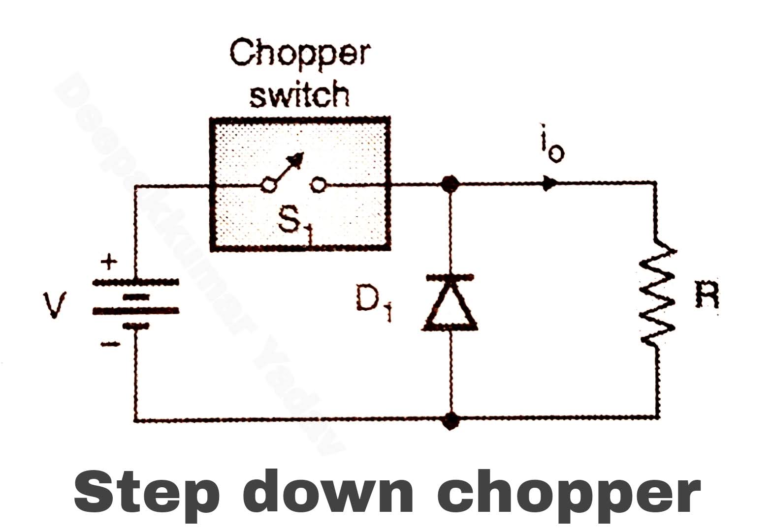
Working of Step Down Chopper

DC Braking Chopper implemented in the simulation model. | Download

Voltage Commutated Chopper Explained - Electrical Concepts