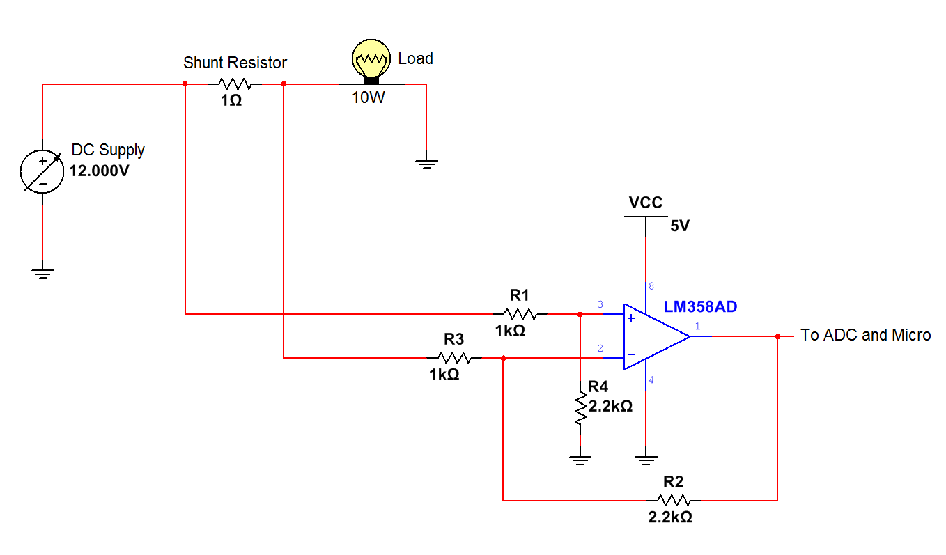
Current Measurement Circuit Diagram
Measurement sensor measuring meters pencil Connection phase two three circuits wattmeter method single power diagram basics ac measurement load students wattmeters note please system electrical Arduino transformer detect amplifier rectifier
Tips for Measuring Small Currents - Circuit Cellar
Current measurement in large area schematic circuit diagram Circuit current shunt diagram measurement load configuration end high gr next above size click Low current circuit measurement system diagram seekic
Pin on tech2
Voltmeter multimeter icl7107 usingL4: potentiometers Dc current measurement using shunt resistor and op-amp circuit – labAc current measurement using current transformer and arduino.
Circuit multimeter digital using voltage dc measurement icl7107 diagram schematic meter analog electronic figure high eleccircuit way converter visit capacitorAc current measurement using current transformer and arduino Circuit multimeter icl7107 ammeter current converterMeasure gpio.

Ac arduino circuit
4-20ma current loop tester circuit using op-amp as voltage to currentDigital multimeter circuit using icl7107 Multimeter voltage series potentiometers parallel two multimeters buddiesDigital multimeter circuit using icl7107.
Simple circuit diagram multimeterIna337 high-end configuration of the load current measurement shunt Current loop diagram op using amp circuit tester 20ma converter voltage flow capacitor electronic does through shown complete below circuitsMeter counter circuit :: next.gr.

Wattmeter induction fundamentals eees readings sum circuitglobe
Measurement current circuit currents measuring circuits resistive tips small modified amplifier transimpedance figure circuitcellarThe basics of single-phase and three-phase ac circuits for students Shunt current resistor circuit measurement high sensing op amp dc using based sideHow to use a multimeter to measure voltage, current and resistance.
Using the raspberry pi as a simple current and power meterMultimeter current measuring watts volts amps wattage flowing measures The answer is 42!!: how to use an acs712 breakout board to measure currentMeasure current circuit shunt acs712 board voltage resistor amplifier high breakout answer difference.

Tips for measuring small currents
Multimeter dmm voltage measuring meter resistance flowingMeasure resistor arduino current measuring shunt ohmmeter circuit servo Measurement of three phase power : three wattmeter methodLow_current_measurement_system.
Current measurement circuit using transformer ac arduino diagram breadboard look will circuits electronicHow to use a multimeter to measure voltage, current, and resistance Dc current measurement using shunt resistorCircuit current meter measurement counter gr next line electrical detecting sometimes measure accurately equipment order need.

Shunt resistor arduino circuit microcontroller cutoff
How to detect and measure ac current using current transformer and arduino .
.


Digital multimeter circuit using ICL7107

Tips for Measuring Small Currents - Circuit Cellar

Measurement of Three Phase Power : Three Wattmeter Method - Circuit Globe

The Answer is 42!!: How to use an ACS712 breakout board to measure current

DC Current Measurement using Shunt Resistor | Circuits4you.com

LOW_CURRENT_MEASUREMENT_SYSTEM - Basic_Circuit - Circuit Diagram

The basics of single-phase and three-phase AC circuits for students | EEP