Counter Circuit Diagram Using Flip Flop
16. the 4 bit synchronous up counter circuit constructed with t Circuit design of a 4-bit binary counter using d flip-flops – vlsifacts Flip flop jk diagram circuit table truth inputs figure fig rs bistable input shown below
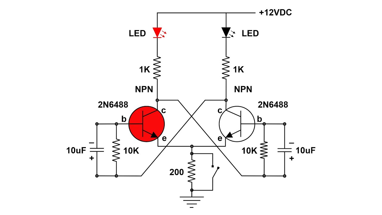
Flip Flop circuits and how they work - YouTube
Binary flops Counter flip flops vhdl should look improve answer stack may Flop flip jk counter bit using ic pinout segment seven
What is jk flip flop? circuit diagram & truth table
Cd4027 jk flip flop pinout, examples, working, datasheet, applicationsJohnson digital counter circuit diagram using d flip flop 7474 (3 bit/4 1: a 4 bit ripple counter circuit. the output of one flip-flop clocksCounter circuit flip flop johnson 7474 using diagram bit simulation animation digital led gr next.
Flip flop circuits and how they workCounter bit synchronous binary flip using flops parallel diagram circuit flipflop here stack gates count Synchronous circuit flops constructedRipple flop clocks count hence asynchronous counters rantle.

Flop circuits
.
.

%2Bwith%2Banimation%2Bsimulation%2Bcircuit.png)
Johnson digital counter circuit diagram using D flip flop 7474 (3 bit/4

flipflop - Parallel binary counter using T flip-flops - Electrical

Circuit Design of a 4-bit Binary Counter Using D Flip-flops – VLSIFacts
Flip Flop circuits and how they work - YouTube

vhdl - How should a counter with R-S flip-flops look? - Electrical

CD4027 JK Flip Flop Pinout, Examples, Working, Datasheet, Applications

16. The 4 bit synchronous up counter circuit constructed with T